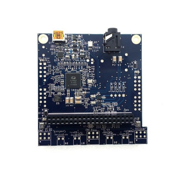


Banana Pi, BPI LCD 1602 Display Module, BPI A 016 1602 LCD Display Module
$9.69
- Brand: Banana PI
- Product Code: bpi-a016-oled-module
- Availability: In Stock
- Ex Tax: $9.69
-
- 2 or more $7.98
- 4 or more $7.01
BPI LCD 1602 Display Module
The RGB1602 Display module is specifically designed for Banana Pi. The module with 1602 LCD screen and it communicates with Banana Pi with I2C. In addition, there are six programmable keys and RGB LEDs on the module. Users can use Python or C(wiringPi) to drive the module with simple and less code.
Product Features
1. 1602 LCD screen
2. RGB LED on board
3. 6 programmable single key
4. Communicate with I2C
5. Can be controlled by the program backlit lights out
4. Port
1. Banana Pi connection port, also can be used on raspberry pi.
Product Parameters
1. Working voltage: 5.0V
2. ASC II string can be simply
3. 4 wires to drive the 1602 LCD screen
4. Use MCP23017 to expand the IO
Typical Application
1. Information Monitoring
2. SchoolEducationall
3. Human-computer interaction
The MCP23017/MCP23S17 (MCP23X17) device family provides 16-bit, general-purpose parallel I/O expansion for I2C bus or SPI applications. The two devices differ only in the serial interface.
MCP23017 – I2C interface
MCP23S17 – SPI interface
The MCP23X17 consists of multiple 8-bit configuration registers for input, output, and polarity selection. The system master can enable the I/Os as either inputs or outputs by writing the I/O configuration bits (IODIRA/B). The data for each input or output is kept in the corresponding input or output register. The polarity of the Input Port register can be inverted with the Polarity Inversion register. All registers can be read by the system master. The 16-bit I/O port functionally consists of two 8-bit ports (PORTA and PORTB). The MCP23X17 can be configured to operate in the 8-bit or 16-bit modes via IOCON.BANK.
There are two interrupt pins, INTA and INTB, that can be associated with their respective ports, or can be logically OR’ed together so that both pins will activate if either port causes an interrupt. The interrupt output can be configured to activate under two conditions (mutually exclusive):
1. When any input state differs from its corresponding Input Port register state. This is used to indicate to the system master that an input state has changed.
2. When an input state differs from a preconfigured register value (DEFVAL register).
The Interrupt Capture register captures port values at the time of the interrupt, thereby saving the condition that caused the interrupt. The Power-on Reset (POR) sets the registers to their default values and initializes the device state machine. The hardware address pins are used to determine the device address.